How do I know if my Laser Doppler Velocimetry (LDV) or Phase Doppler Particle Analysis (PDPA) transmitting optics are forming a good measurement volume? What am I looking for?
These are good questions. In order to achieve high-quality and accurate LDV and PDPA measurements, we want the best quality laser beams as possible.
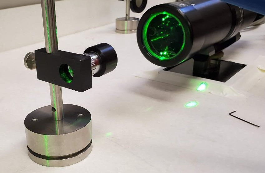
Commonly, we look at the measurement volume with a microscope objective, to allow a magnified view of the light intensity distribution there. Set up the transmitter and microscope on an optical table or smooth flat surface, with 3 – 5m of distance ahead of it to the nearest wall. A light-colored wall is better.
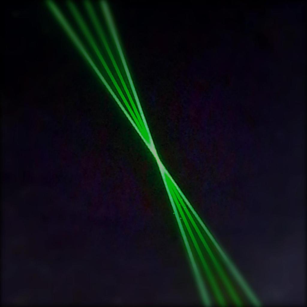
Open one pair of beams. Carefully move the microscope objective into the measurement volume. You will see the two beams merge, then unmerge as you move the microscope objective along the optical axis of the transmitter.
The overlap when you position the microscope objective at the beam crossing, should be at least 90%.
Now put the microscope objective where the most beam overlap appears to be. This will be in the center of the crossing region (green beam shown here):
What kind of pattern do you see? Turn off all beams except one, and examine each in turn.
Here are some possibilities of what you may see:
Rings
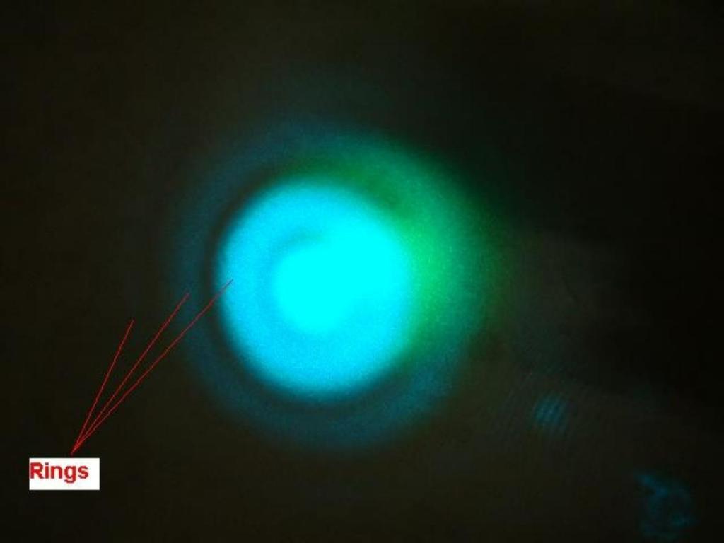
Rings usually result from contamination of the very ends of the optical fibers, in the probe. Poor ‘collimation’ can also cause rings, but these rings are usually wider and fewer in number. A large hole may also appear in the center of the spot. Rings will prevent you from taking accurate data, although the system will still appear to work. The validation rate may drop. The measured velocity may be unreasonable. Many microscope objectives have slight defects that cause ring patterns to appear when the beam passes through certain locations of the objective’s lenses. Be sure you are not seeing a ring pattern due to the microscope objective, by slightly moving it around, to allow the beam to pass through a different part of the lens.
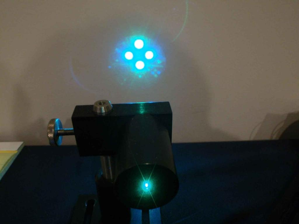
Speckle
These beams are well-aligned and appear to have high quality Gaussian, however there is some amount of speckle (small dots of light randomly located around the 4 primary beams).
A speckle pattern usually results from stressing the optical fibers. It could be at the input (i.e. coupler) end, or the probe end. If you’ve recently reset the polarization at the input end of the fibers, you may have over-tightened the 0.035 set screw(s). This may also be an age-related issue. Expect the polarization to be unstable in this case as well.
Speckle is not a showstopper. Most beams will have some degree of speckle, and it has little to no effect on the measurements.
Hole Pattern
A hole in the center of the beam usually results from contamination of the optical fiber at the probe end. One or more rings may also appear. The symptoms will be similar to Rings, and you may have trouble getting the usual amount of beam power in the probe volume.

This is what a clean properly collimated beam pattern should look like. There may be one faint wide ring around the center spot.
High quality laser beams can help you achieve the best results possible with your LDV or PDPA system. If you have any questions or would like help improving the beam quality or beam alignment of your LDV system, feel free to contact us through the contact page. We would be happy to help.
